Overview
The project goal is to analyze and recreate an
airfoil based on the NACA number. Then test and record the airfoil in simulated
conditions. Then create an airfoil and test it to see if it matched the
characteristics of its simulated counterparts.
airfoil based on the NACA number. Then test and record the airfoil in simulated
conditions. Then create an airfoil and test it to see if it matched the
characteristics of its simulated counterparts.
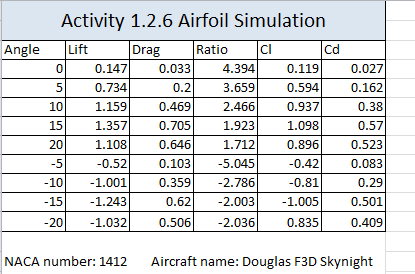
Douglas F38 Skynight (F-10)
(NACA 1412)
The Douglas F3D Skynight is a twin engine, fighter jet.
It was manufactured by the Douglas Aircraft company in El Seguido California.
It was designed as a carrier based all weather night fighter.
It is a mid-wing.
It was manufactured by the Douglas Aircraft company in El Seguido California.
It was designed as a carrier based all weather night fighter.
It is a mid-wing.
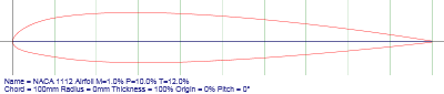
Airfoil Data
Getting the vital data based on the NACA number
involved looking up the NACA number for the chosen airfoil, and plotting its
profile. We used the NACA 4 digit series profile generate to get the profile.
This profile is used to create the airfoil for testing.
involved looking up the NACA number for the chosen airfoil, and plotting its
profile. We used the NACA 4 digit series profile generate to get the profile.
This profile is used to create the airfoil for testing.
|
|
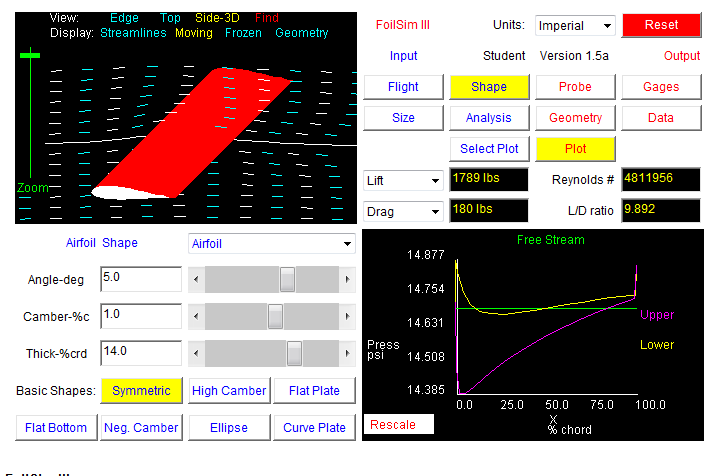
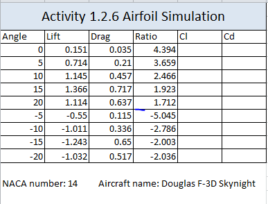
Nasa Website Airfoil Sim Data

Construction
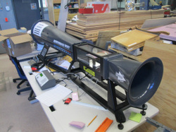
Construction of the airfoil was acheived by
sandwiching 2 inches of foam between identical airfoil cross-sections made of
3/16" plywood. The foam was then cut out and sanded to match the
cross-sections, and then the cross sections were removed and mounting clip was
attatched. The scaled profile of the airfoil were used to create the
cross-section pieces that served as the guideline for the airfoil itself.

|
The airfoil was put into a wind tunnel and tested
from -20 degrees Angle of Attack to +20 degrees Angle of Attack at 5 degree increments. Before testing, the same experiment was performed using the NASA Foilsim app set to the exact same conditions to calculate the lift/drag coefficient. Since it is a ratio, the scaling of the airfoil should have no effect on the outcome. |
Test Results
|
NASA Website Results
|
|
Wind Tunnel Results
|
Conclusion
1. Explain differences between the airfoil simulation prediction and
the wind tunnel test results.
The differences between the airfoil simulation and wind tunnel are that they both had different outcomes of the lift and drag.
2. What
characteristic of the airfoil had the most significant impact on lift and
drag?
The most signifigant that impacted the airfoil was how well I created and designed my airfoil.
3. Explain what you would
change in the design of your airfoil design?
What I would in the airfoil design is how much time I took to make my airfoil since the more time I take to carefuly make the airfoil. The better the airfoil would have been when it was the windtunnel.
